Sponsored by:
![]()
You can also choose to use TommieBot, an AI search assistant developed by St. Thomas School of Engineering students and faculty.
Take me to TommieBotProject Summary
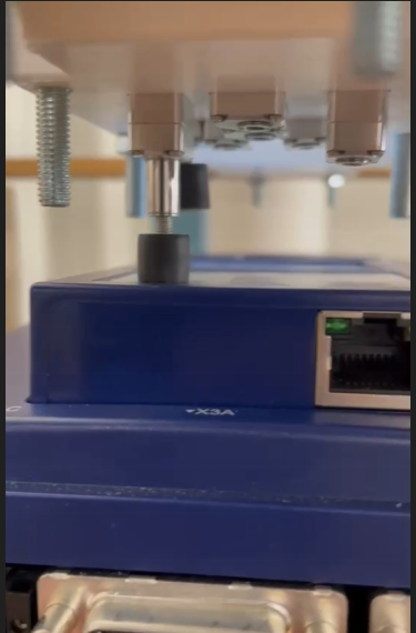
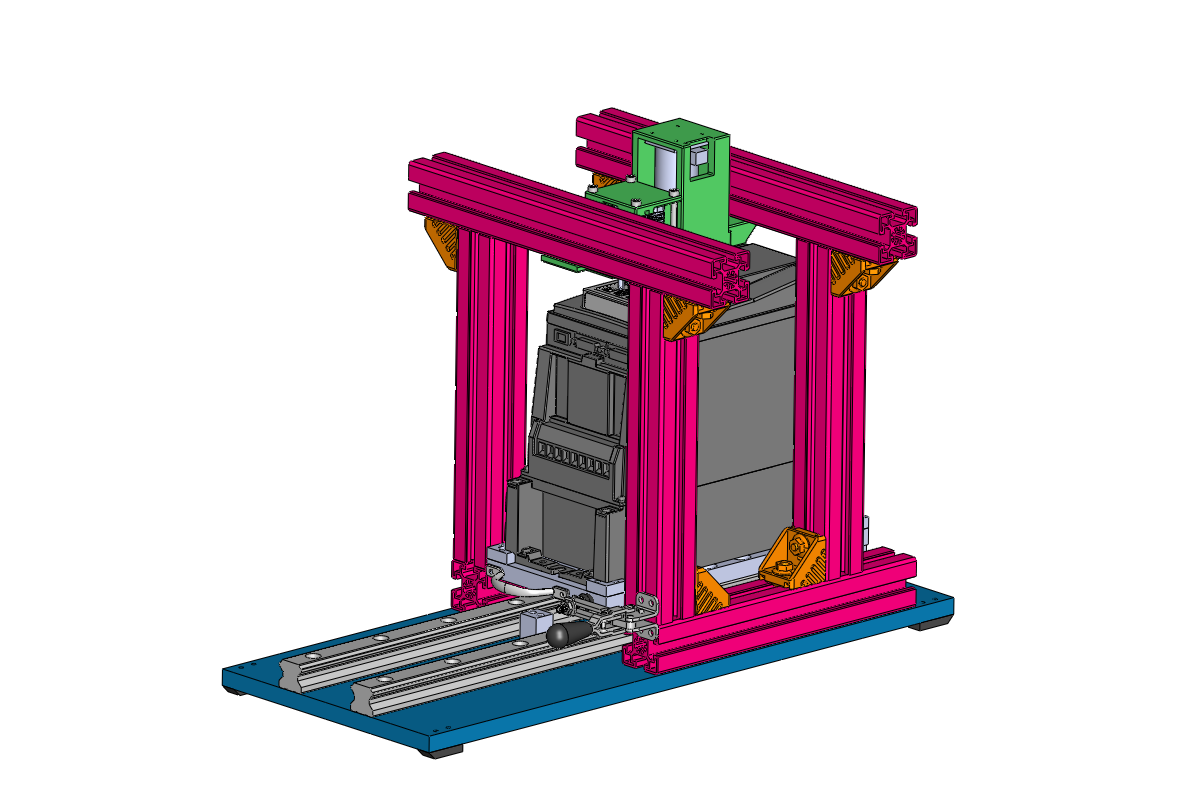
KEB America has requested an automated fixture to function test the VFD controller interface for their new F6 product line. The value this has to KEB is that Testing can now be performed with reduced personnel resources in R&D to balance productivity. Additionally, new firmware updates can be readily tested with software presets on the machine, streamlining the process in R&D. The solution consists of an eight linear actuator array to press the buttons. A program is used to prepare test parameters, and a Raspberry Pi camera capture system works in tandem with the program to provide results from the remote’s screen after each of the button presses. This system can be interfaced with via network connection over ethernet, with the corresponding results from the camera capture system being stored in a database for the end user to identify where the VFD passed or failed each test.
Design Goal
The goal of the project is to create an automatic tester that runs through a user-created testing sequence. A sequence of buttons and related screens will be specified such that the automated system will press each button and verify that the controller is functioning correctly. Using computer vision, a comparison of the resulting remote screen with the expected screen will send a pass or fail result to an accessible database.
Design Constraints
Download the project summary (PDF file).
Sponsored by:
![]()
Student Team:
Industry Representative: Andrew Sanchez and Michael Belsky
Faculty Advisor: Ray Haremza
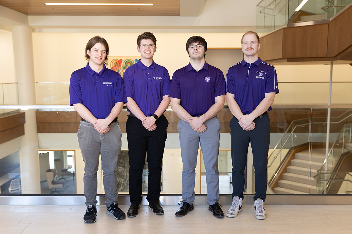
Pictured left to right: Ciaran Macken, Joe Hibbard, Lance Munsterteiger, Daniel Walczak.